Site perso : Emmanuel Branlard
Next: 12. Compressors | Up: 11. Dipoles | Previous: 11.2 Dipole fields from measurement |
Navigation: Contents | Index
- 11.3.1 Modelization of dipoles in Astra
- 11.3.2 Comparison of the different fields
- 11.3.3 Fit with Henge's field fall-off model
11.3 Comparisons between dipole measurements and Astra modelization
11.3.1 Modelization of dipoles in Astra
In Astra, dipole magnetic fields are modelized as follow :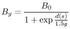 |
(11.8) |
where
 (a) (a)
 (b) (b)
|
11.3.2 Comparison of the different fields
We are still studying here the trapezoidal dipole of A0. For this dipole, the beam is suppose to enter at

|
11.3.3 Fit with Henge's field fall-off model
The measured fields from exp3 have been fitted with several Henge's fringe field model(see section 11.1.3). Henge model is function of a polynome. We fitted the measurement data for Henge fields with polynomes of degree one, three and five. In a sense, Astra corresponds to a Henge model with a polynome of degree 1, without any constant. Nevertheless, the Henge field for a polynome of degree one that fits best the measured field is far from Astra fields. The different fitted fields are plotted on figure 11.7. To compare the different fits, the integral of the field has been calculated, and compared to the integral for the measured field. If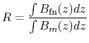 |
(11.9) |
note that here we don't integrate on the trajectory of the particle, but on a straight line defined by

|
From figure 11.7 we clearly see that one needs to implement a better field modelization in Astra. The other solution for the simulation, is to increase the field amplitude, of the current by a factor of 1.5(=1/R), or reduce the radius by a factor of 0.64 (=R). The underestimation of about 0.64 explains why the radius obtained by Astra when fitting the geometry of a0 or NML are smaller from a factor 1.5 compare to the real radius (see table 12.1 and 13.1).
Next: 12. Compressors | Up: 11. Dipoles | Previous: 11.2 Dipole fields from measurement |
Navigation: Contents Index